CJR Performance Dynojet PV3 Setup Guide
CLICK HERE TO WATCH OUR YOUTUBE VIDEO OF THE WALKTHROUGH!
STEP 1 - CHECK/UPDATE TO THE LATEST FIRMWARE
Now that you have your Dynojet PV3, you may be wondering where to start. This step by step guide will walk you through the process! We’ll begin with the PV3’s firmware, and move into flashing your vehicle.
-
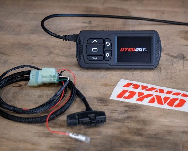
Remove your Dynojet PV3 from the box and plug into your computer using the supplied USB cable.
-
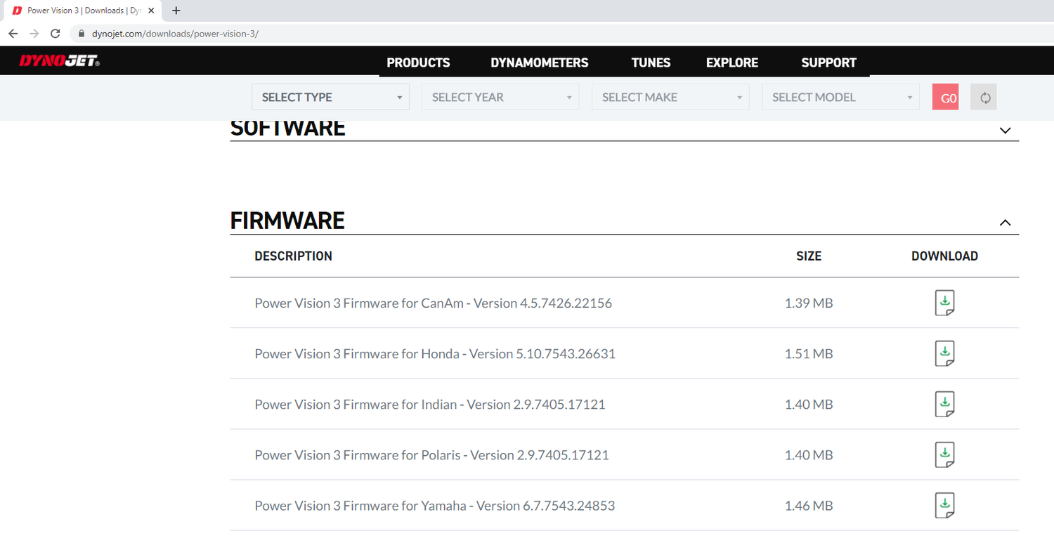
Head over to https://www.dynojet.com/downloads/power-vision-3/ - Scroll to the bottom and click the firmware tab as shown in the image. We want to ensure the latest update is on the PV3 before getting started.
-
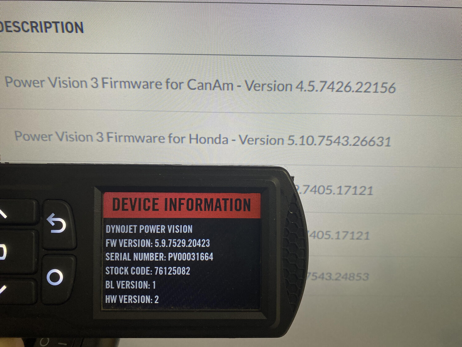
On your Dynojet PV3, click the center rectangle button to enter the menu -> Scroll down to device tools -> Scroll down to device information. Verify the “FW VERSION” matches that of the Dynojet firmware description.
-
Here is an example of a firmware not up to date. You can see the firmware shown on the PV3 is 5.9.7529.20423 and the file needed is 5.10.754326631. This is a firmware update to be used with the Honda. Click download to save this file, it will automatically save in your “downloads” folder.
Our next step will be dropping the firmware update download file onto the Dynojet PV3 as shown in the image below. While the PV3 is connected to the computer it acts as a USB drive. You will do this by opening the file explorer in 2 separate windows, or dragging it directly from the downloads folder to the “POWERVISION” tab located on the left side.
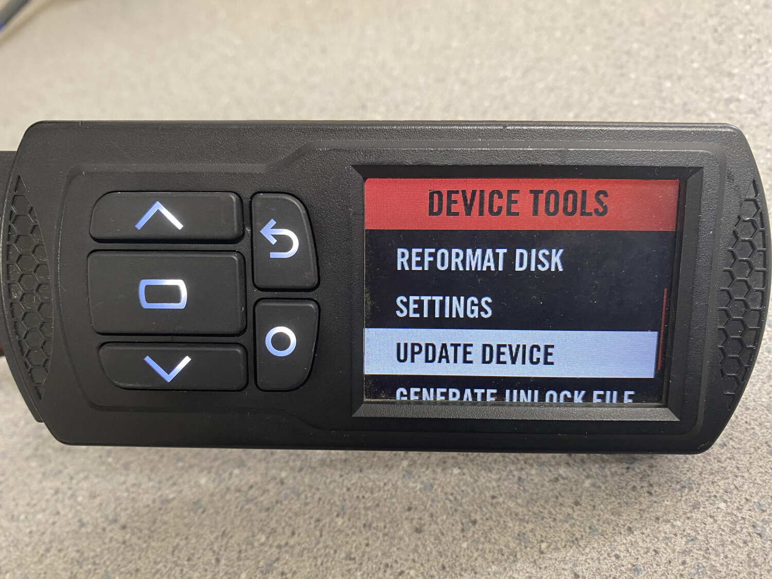
Next, we will need to manually update the device - From the gauge menu, select “enter” to open the main menu, scroll down to device tools -> Scroll down to update device as shown in the image below.
From here you will need to verify the update file is located on the PV3 as shown -
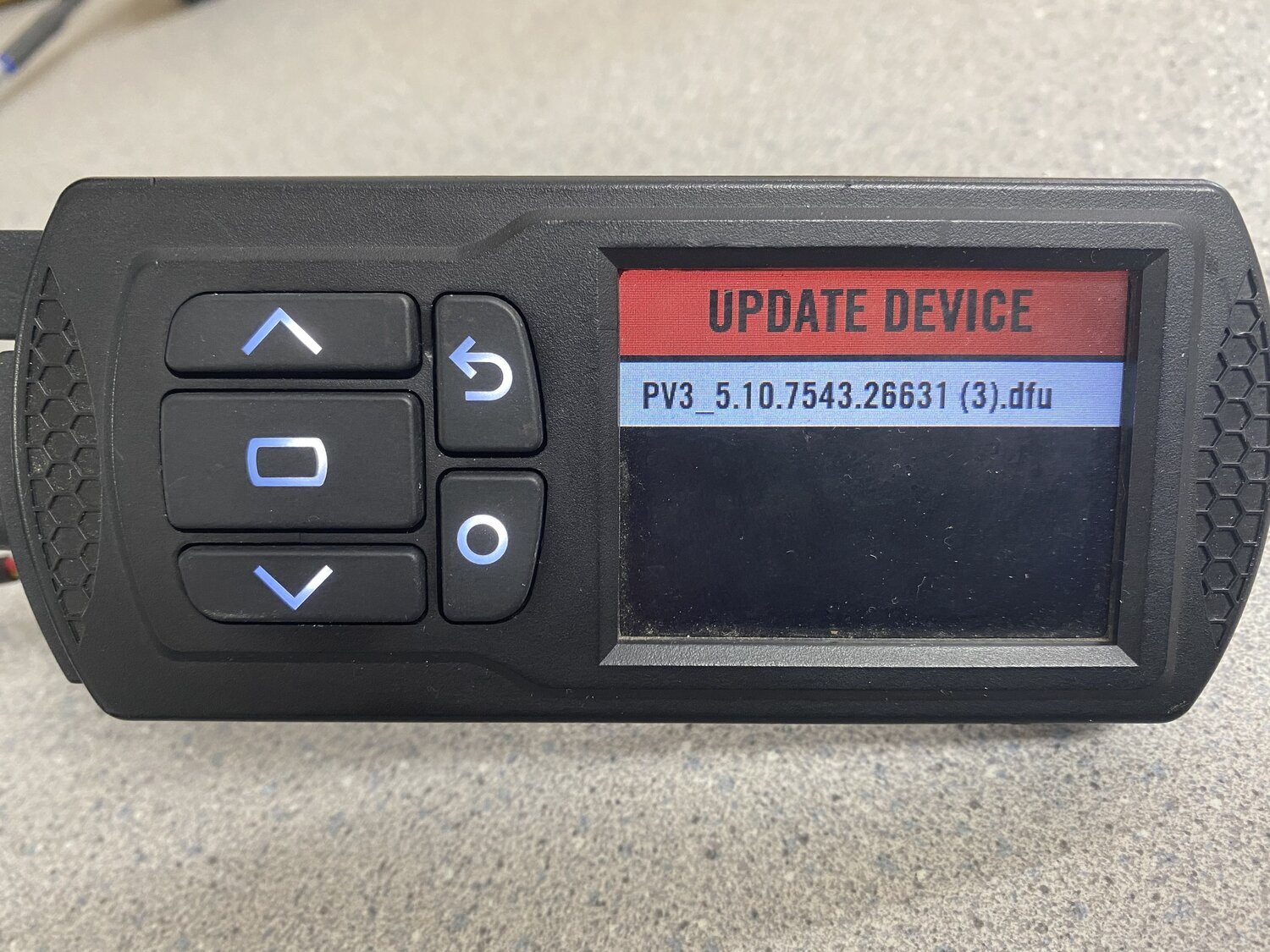
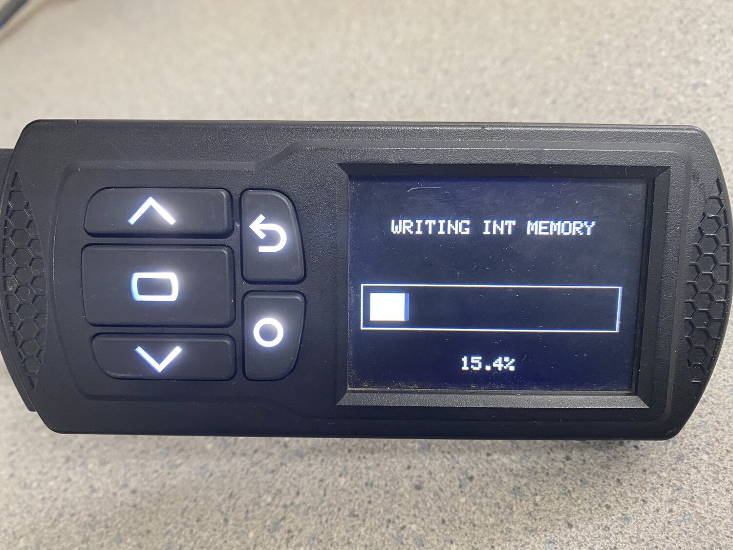
Select the update file, and begin the update. The PV3 will flash and update in the bootloader. It will restart once completed.
Now that your firmware is up to date, we will begin flashing the vehicle in step 2.
STEP 2 - INSTALLATION + FLASHING THE STK FILE
-
STK File = Dynojet Stock Tune File / DJT File = Dynojet Modified Tune File (An STK file is an OEM fuel/ignition map file with dynojets coding integrated)
-
With the updated firmware, it is time to locate the diagnostic port found on your vehicle. Instructions will be found in the box with the PV3 to locate the plug. Honda generally uses a red 4-pin or 6-pin connector.
-
With the PV3 plugged into the diagnostic port, turn the key (and kill switch) to the on position and wait for the PV3 to startup and check for files. Once running, 4 gauges appear, click enter (big center button to enter the menu), click “flash vehicle”, and select the STK file. This generally appears as such 0102130501.STK. Each model will have a different number however the “.STK” will designate a stock tune file. - If no files appear, contact CJR or Dynojet for assistance. You may need to press the circle to change from STK to DJT files. An STK file will need to be flashed into the vehicle before a DJT file can be loaded.
-
The STK file is Dynojets stock ECU tune file. A “DJT” file is nothing more than a modified STK file. Once the STK file has been flashed to the ECU. You will be able to access the PV_Info.txt file for available tunes as shown in step 3.
STEP 3 - ACCESSING DYNOJET AND CJR SPEC TUNES
-
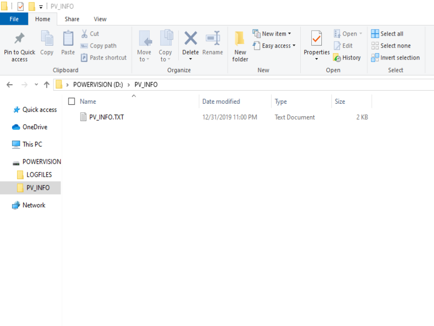
Plug the PV3 into the computer and open “POWERVISION” in the windows explorer. Select the PV_Info folder and open the folder to access the PV_Info.txt file.
-
This “PV_Info.txt” file will be used to access free Dynojet tunes located here - https://www.dynojet.com/tunes/
-
If purchasing a tune from CJR, or a PV3 purchased from CJR that comes with a free tune, you will need to drag/drop the PV_Info.TXT file as an attachment and email the file over to CJRPerformanceLLC@gmail.com, we require this file to email over your new tune.
STEP 4 - FLASHING YOU DJT FILE
-
Once you download the tune from Dynojets website or receive an email with the CJR off the shelf tune, you will need to simply drag and drop the file onto the power vision located in the windows explorer menu. We recommend saving the file to your computer first and then dragging the file over, some customers have reported the file to become corrupt if dragged directly from the email, to the PV3. Ensure the file is only opened with the Dynojet C3 software. If the file is opened with another program, even microsoft word for example by mistake. It can corrupt the tune file.
-
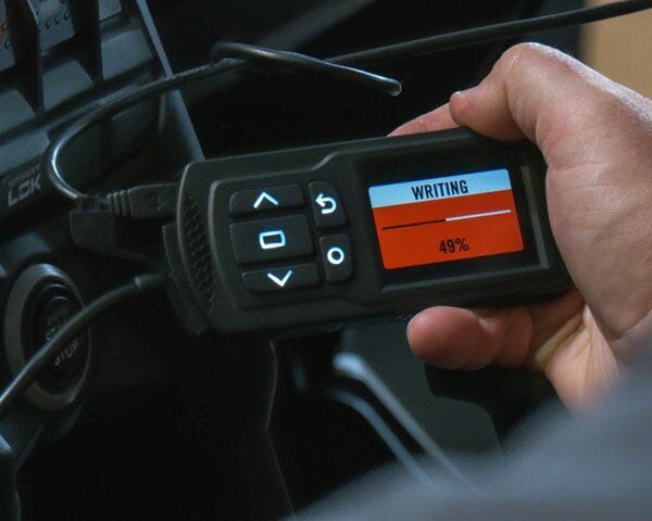
From here you will follow the same steps as previously to flash the STK file, however this time you will flash in the new DJT file. Once loaded you will need to key off, then back on to verify the flash has completed.
-
Once the flash has been completed, you are ready to ride! If you have any issues or would like the tune to be check over, you may send us a datalog to review.
Flashing multiple ECU’s with Dynojet’s PV3.
Step 1 - Plug the Dynojet PV3 into the NEW bike with the non-flashed OEM ECU. Turn the key on, kill switch to the on position, and the Dynojet will power on.
Step 2 - Just like you did with the first bike, flash the .STK file into the ECU. Do this by pressing enter (rectangle) to open the menu, again to enter “flash tune”, and choose the stk file.
Step 3 - After flashing the STK file into the new ECU, it will bring the new information onto the PV3 regarding the new ECU. Without connecting the PV3 to any other bike, plug the PV3 into the computer/laptop. If you happen to plug the PV3 into another bike before connecting to a laptop, repeat step 1 and start fresh. Open the “file explorer” icon on your computer and click “power vision”. Remember while the PV3 is plugged into the computer, it acts similar to a flash drive. There will be a folder called PV_INFO, open the folder and attach the file called “PV_INFO.txt” onto an email to CJRPerformanceLLC@gmail.com. In the subject line, type “DYNOJET TUNE LICENSE”. We will reply back shortly with a code which may be used at checkout.
Step 4 - To pay for the license head over to https://cameronjonesracing.com/products/cjrpv3etune and purchase “Dynojet Tune License”. At this time you will enter your modifications for the new bike, if a tune is available to match the modifications, we will send it back with the license file. If we do not have a tune available, we will notify you of the nearest option.
Step 5 - After purchase is complete, we will process the tune license with Dynojet and email back the license file. It will be named “xxxxxxxxx.LIC”. Drag and drop this file onto the PV3 where the other tunes are located. ***Do not drag and drop the file into the “PV_Info” folder or any other folders.
Step 6 - Flash the ECU again with the proper .DJT file and your second bike is paired with the PV3. At this time, the ECU is sync’d with the second bike. If the PV3 goes back to the first bike to change tunes or view data, it will need to go through the pairing process located below.
*PAIRING PROCESS - Anytime you switch from bike to bike on the same PV3, you will need to sync the PV3 and current ECU. If you do not, the gauges on the initial display will not view live data with the recently attached bike. To sync the PV3 and ECU after switching to the new bike, simply flash the same tune back into the ECU that corresponds to that bike.
Datalogging with the Dynojet PV3
-
Once your dynojet PV3 is paired to your ECU. You may record a lot of valuable ECU information in which the PV3 has to offer. This can be viewed in the C3 software, or you may send the file to use for analysis in which we do require the WBCX kit for fuel adjustments on most models.
-
Recommended Datalogging Setup - We recommend configuring gauges in a way they are easy for you to monitor important factors. One of the most important being the throttle position, or TPS (Throttle Position Sensor). We also recommend having engine RPM, AFR (with the WBCX kit), and engine oil temp on the first display. We recommend getting the bike up to full operating temp before starting a log, unless you are trying to record the warm-up session itself if there are issues with startup. Generally recommended oil temp is between 180-220*F
-
Datalogging - Find a good area or track in which you can build smooth, consistent data. We aim to have customers give us 25%, 50%, 75%, and 100% throttle passes. For this, keep an eye on your TPS gauge, generally this is going to be in relation to the DEGREES in which the throttle is turned, and not % of throttle. You can see what the total TPS is on the Dynojet software, or click a higher gear and give full throttle input to see what the max value is indicated on the gauge. Generally 72*-79* is common for 100% throttle. We are looking for various pulls of different controlled throttle input, this will help build a base map quickly and start fine tuning. 20% increments and 25% increments are most common up to 100%. Example - 20%, 40%, 60%, 80%, 100% or as mentioned above, 25%, 50%, 75%, 100%
-
We are going to use 25%/50%/75%/100% for our example. If your max TPS is shown as 74* on the gauge an easy way to check for throttle position would be dividing.
-
74 divided by 2 = 37 (37 is used for 50% throttle)
-
74 divided by 4 = 18.5 (18.5 is used for 25% throttle)
-
37 + 18.5 = 55.5 (this would be your 75% throttle mark)
-
So your target TPS % to what is viewed on the gauge for 25% = 18.5, 50% = 37, 75% = 55.5 and 100% = 74
-
-
For lower throttle inputs, like 20% to 25% increments. Start in a lower gear like second, bring the RPM down to low around 2,000rpm and crack the throttle to display TPS = 18 to 19 as shown on the gauge. Hold that 18/19 from 2,000rpm to redline. Next you may click up a gear for 50%, 75%, and 100% may be used in 4th/5th.
-
All bikes will be different as some may not be able to redline 25% in second gear, if this happens you may try first gear. The goal is recording data over a longer period of time compared to a quick burst. All of these can be done within the same datalog, or individual logs.
Below is an example of both good, and not so good data from a customers log for us to view. Holding an exact TPS can be challenging so sometimes these movements of data shown in blue and red are normal. As you can see in the green and orange line, the TPS of 49* is held very steady, this indicates about 45% throttle and the wide open orange line 74* is straight as can be. The red and blue line both show where the rider gave slightly too much, followed by too little throttle before leveling off fairly flat. As you can see the graph at the bottom shows time, where red and blue where taken in a lower gear, and orange and green were both in a higher gear.
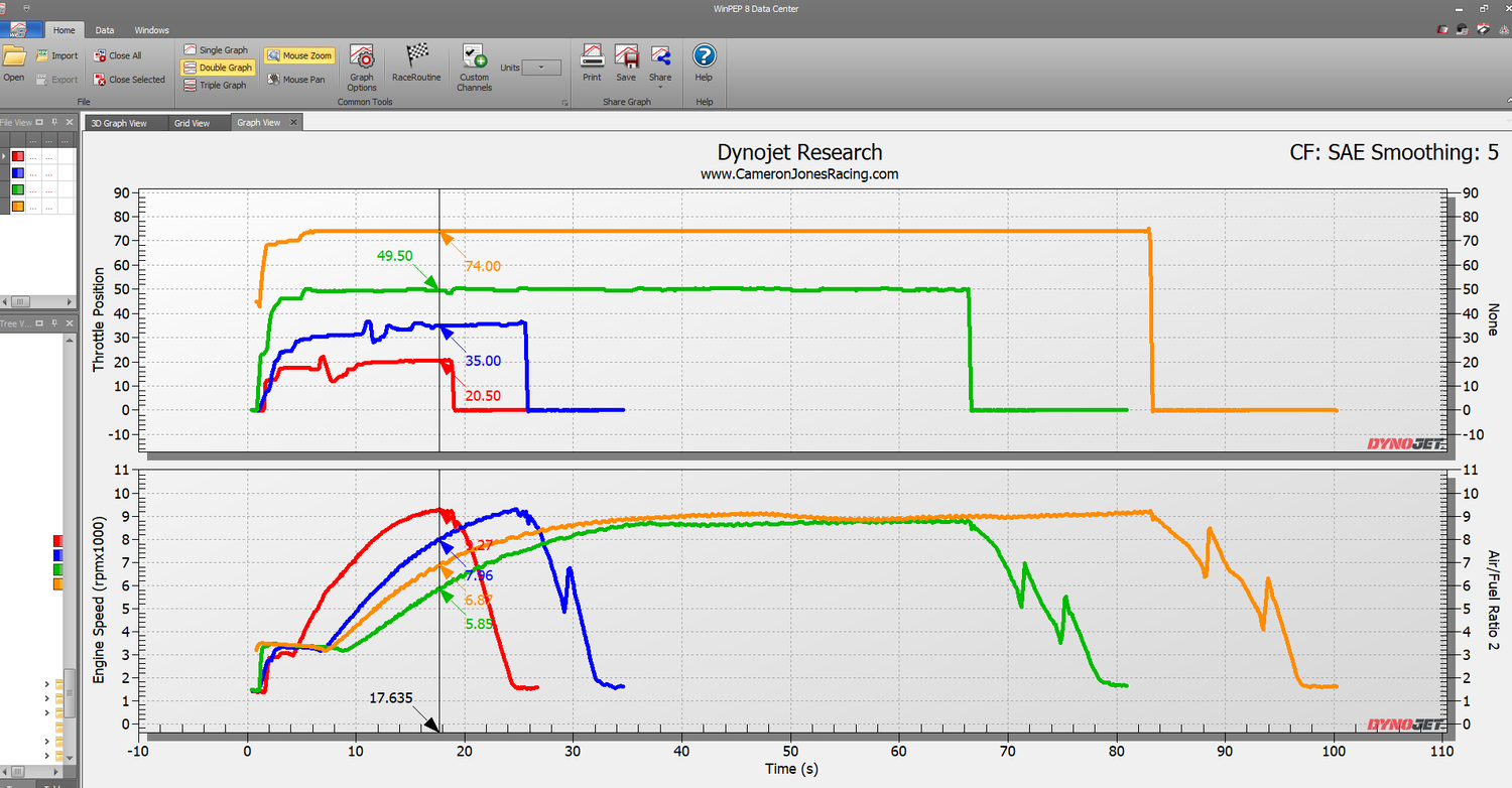
Keep in mind getting “perfect” TPS over the rpm is ideal, keeping it within 5* still good data for us to view.
If datalogging with CJR for remote tuning, after recording the datalog with 25%/50%/75%/100% throttle, you will need to plug the PV3 into the computer and pull the log file from the power vision 3. From here, you will need to email the file via drag/drop or attach the log file as well as your current tune used during the datalog session. Email both files to CJRPerformanceLLC@gmail.com. We will review the data, update the tune and send back a corrected file. From here these steps will be repeated until the final tune we will re-enable certain settings within the ECU for closed loop/autotune adjustments.